HOW TO ORDER, Selection Example
How to order-Information required when ordering standard gear units
|
Prime Mover |
|
|
1. |
Type - electric motor or engine, for example 4 cylinder internal combustion engine |
|
2. |
Power rating in kW |
|
3. |
Output speed. If variable, indicate speed range and frequency of variable. |
|
4. |
Dimensions of prime mover. |
|
Driven Machine |
|
|
1. |
Type, for example, kiln, conveyor, etc. |
|
2. |
Power rating in kW |
|
3. |
Speed |
|
4. |
Service - hours per day, running time in any hour, details of reversals if applicable, type of loading, ambient temperature, etc. |
|
|
|
|
1. |
Type, for example, H2. |
|
2. |
Size, for example, 315. |
|
3. |
Ratio |
|
4. |
Shaft handling. Refer to dimension pages and quote reference. |
|
5. |
Direction of rotation (for units with right angle shafts refer to handling diagrams on dimension pages). If holdback arrangement is to be fitted, please indicate the direction of rotation of low speed shaft looking towards it. |
Shaft Connections
1.
Couplings Quote shaft diameters with tolerances or coupling bores.
2.
Details of overhung loads, including diameter and type of sheave, sprocket or pinion and any thrust loads.
Shaft mounted units for High Inertia Drive
When used on Traverse drives with inertia driven loads, e.g. crane drives (slewing, long travel and cross travel) bogie drives and selected high inertia load roller table drives, it is recommended that shaft mounted units should be fitted with shock absorbing Torque Arms. Consult us with specific application details.
Example 1
A foot mounted parallel shaft speed reducer is to be directly
coupled to a 750 kW, 1500 rpm motor. The output shaft is to
rotate at 365 rpm and is coupled to a large industrial fan
absorbs 725 kW on 24 hours/day service. The maximum ambient
temperature is 300C.
Selection
|
1. |
Gearbox Type |
|
1.1 |
Parallel shaft type is specified - type H. |
|
1.2 |
Ratio
=1500÷365 |
|
2. |
Mechanical Capacity |
|
2.1 |
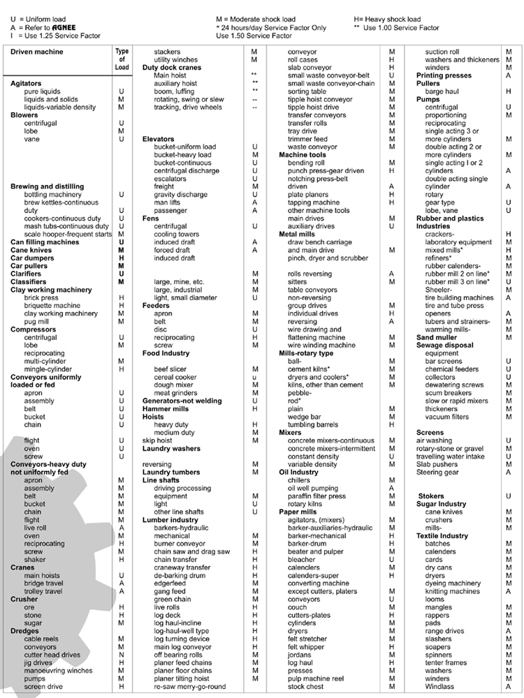
From table 3 on previous page the application is moderate shock. |
|
2.2 |
From table 1 on page 3 the service factor is 1.5. |
|
2.3 |
The required mechanical capacity = 1.5 x 725 = 1088 kW |
|
2.4 |
Under mechanical ratings a unit size 315, nominal ratio 4.13, has a capacity of 1293 kW |
|
3. |
Thermal Rating Check |
|
3.1 |
From table 2 on previous page the thermal service factor for 300C ambient temperature and 100% running time is 0.9 for a unit with fan cooling (reference to the thermal ratings shows that at least fan cooling is required.) |
|
3.2 |
The required thermal capacity = 725 - 0.9 = 806. |
|
3.3 |
Under thermal ratings, fan cooled, a size 315 has a capacity of 918 kW at 1500 rpm, ratio 4.15 |
|
4. |
Check that the exact ratio. |
|
5. |
Order a gearbox type H1 - 315 exact ratio 4.15 with cooling fans fitted. |
Example 2
A shaft mounted gear unit right angle shafts is required to
drive a belt conveyor running 24 hours/day at 80 rpm. The unit
must have feet for the attachment of a motor mounting
baseplate. The motor is 500 kW at 1500 rpm and the absorbed
power at the conveyor headshaft is 465 kW. The ambient
temperature on site is 200 C.
Selection
|
1. |
Gearbox Type |
|
1.1 |
Foot shaft mounted unit with right angle shafts. |
|
1.2 |
Ratio = 1500÷80 = 18.8, type B2SF could be used |
|
2. |
Mechanical Capacity |
|
2.1 |
From table 3 on page 10 the application is uniform load. |
|
2.2 |
From table 1 on page 3 the service factor is 1.25 |
|
2.3 |
The required mechanical capacity = 1.25 x 465 = 581 kW |
|
2.4 |
Under mechanical ratings a unit size B3SF - 400, nominal ratio 18.9, has a capacity of 620 kW. The double reduction type B2SF - 400 ratio 18.9 has insufficient mechanical capacity. |
|
3. |
Thermal Rating Check |
|
3.1 |
From table 2 on previous page the thermal service factor for 200 C. ambient temperature and 100% running time is 1.0 |
|
3.2 |
The required thermal capacity = 465÷1.0 = 465 kW. |
|
3.3 |
Under thermal ratings, fan cooled, a size 400 at 1500 rpm has a capacity of 484kW |
|
4. |
Check that the exact ratio. |
|
5. |
Order a gearbox type B3SF - 400, exact ratio with cooling fans fitted. |
OVERHUNG LOADS / AXIAL THRUST LOADS - HORIZONTAL UNITS
|
p |
= |
kW x 9545 x K ÷ N x R |
|
|
Where P |
= |
equivalent overhung load in kN, |
|
|
kW |
= |
power carried by the shaft, |
|
|
N |
= |
rpm of the shaft |
|
|
R |
= |
pitch radius of sprocket, pinion, sheave or pulley (mm). |
|
| Overhung member |
K Factor |
||
|
Sprocket for chain |
1 |
||
|
Spur gear |
1.25 |
||
|
V belt sheave |
1.5 |
||
|
Flat belt pulley |
3.0 |
||
|
|
|||
|
1. |
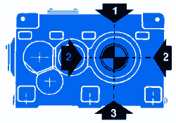
Values are calculated for the most unfavourable direction of rotation. Consult us with specific application details. |
||
|
2. |
Overhung loaad values are for loads applied midway along shaft extension. | ||
|
3. |
For overhung load and axial thrust values for large sizes consult us. |
||
|
|
|||
|
Direction |
Output |
Types H2-H3-B2-B3 |
|||||||
|
200 |
225 |
250 |
280 |
315 |
355 |
400 |
450 |
||
|
1 |
315 |
35 |
42 |
47 |
56 |
78 |
100 |
100 |
172 |
|
200 |
40 |
48 |
57 |
68 |
87 |
118 |
126 |
190 |
|
|
125 |
48 |
55 |
62 |
85 |
103 |
132 |
150 |
228 |
|
|
80 |
52 |
68 |
78 |
97 |
130 |
162 |
190 |
280 |
|
|
50 |
52 |
68 |
90 |
126 |
148 |
182 |
228 |
320 |
|
|
31.5> |
52 |
68 |
90 |
126 |
148 |
182 |
230 |
320 |
|
|
2 |
315 |
35 |
42 |
47 |
56 |
78 |
100 |
109 |
172 |
|
200 |
40 |
48 |
62 |
85 |
87 |
118 |
126 |
190 |
|
|
125> |
41 |
48 |
62 |
85 |
99 |
120 |
150 |
215 |
|
|
3 |
315> |
18 |
23 |
30 |
42 |
49 |
61 |
78 |
107 |
|
Type of |
Unit Size |
|||||||
|
200 |
225 |
250 |
280 |
315 |
355 |
400 |
450 |
|
|
H2-H2S-H2SF |
8.45 |
10.5 |
13.0 |
19.5 |
26.5 |
32.2 |
38.7 |
45.8 |
|
H3-H3S-H3SF |
3.03 |
4.58 |
6.45 |
8.4 |
10.5 |
13.0 |
20.0 |
28.9 |
|
B2-B2S-B2SF |
12.0 |
15.6 |
19.6 |
25.4 |
30.6 |
36.0 |
41.3 |
49.8 |
|
B3-B3S-B3SF |
3.03 |
7.12 |
8.90 |
12.0 |
15.6 |
19.6 |
25.4 |
30.6 |
Table 6 :
Permissible Axial Thrust on Low Speed Shaft (kN)
(Horizontal Units)
|
Output |
Type H2-H3-B2-B3 |
|||||||
|
200 |
225 |
250 |
280 |
315 |
355 |
400 |
450 |
|
|
315 |
12.0 |
12.5 |
13.4 |
11.8 |
18.3 |
30.3 |
28.8 |
53.4 |
|
200 |
13.4 |
14.2 |
15.2 |
13.3 |
20.8 |
34.3 |
32.6 |
60.5 |
|
125 |
17.1 |
17.3 |
18.0 |
18.4 |
25.3 |
40.0 |
40.9 |
70.8 |
|
80 |
18.2 |
20.5 |
21.8 |
23.8 |
35.6 |
63.6 |
55.4 |
80.85 |
|
50 |
19.4 |
25.8 |
25.3 |
32.1 |
43.5 |
66.3 |
68.5 |
94.3 |
|
31.5
and |
19.4 |
25.8 |
25.3 |
34.3 |
55.6 |
66.3 |
88.6 |
94.3 |
LOAD CLASSIFICATION BY APPLICATION